Tuesday, 27 February 2018

Create New Geometry

When creating new geometry (e.g. VertexCreator), use the CoordinateSystemSetter transformer to define the coordinate system.

---

To change the geometry of a line (or polygon) into a single point at its start or end, you can use the Snipper transformer, setting the [Snipping Mode] to [Vertex], and setting the two indexes to [0] for the first vertex, or to [-1] for the last vertex:


---

To create a line or polygon from an array of coordinates, you can use the VertexCreator transformer with the [Mode] set to [Add Point]. However, this doesn't work if there are duplicate points other than start = end in the array.


Instead use the VertexCreator transformer with the [Mode] set to [Replace with Point], followed by a LineBuilder transformer. On the latter, make sure you connect the [Line] or [Polygon] output port!


Get X & Y

To get the X and Y coordinates as attributes, you can use the CoordinateExtractor transformer, using index 0 for the first vertex and index -1 for the last.

Raster Checking

Before processing a raster, check the raster. After loading the raster in the Data Inspector, select the Information button and drag a box to show the raster details.

Clicking in the raster, shows the raster cell details of the clicked cell.

Raster Bands

If the raster is a colour raster, i.e. an image, it should have 3 bands displaying the RGB values;
If the raster is a numerical raster, e.g. a DTM, it should have 1 band displaying the numerical value.

To remove any unwanted bands (e.g. alpha band), use the RasterSelector transformer followed by the RasterBandKeeper or RasterBandRemover transformer.


To separate the RGB bands, use the RasterBandSeparator transformer.

Raster NoData

NoData by default means no colour = transparent.

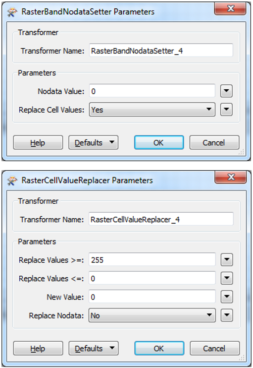
To set the raster's NoData value on a numerical raster, first define the NoData value using the RasterBandNodataSetter, followed by a RasterCellValueReplacer setting all values outside the valid domain to the newly selected NoData value.

Raster Display

To display a raster, use the RasterInterpretationCoercer transformer.

Python: Get Filename and Folder Name

Filename


# Get the full name of the input DWG file
s1 = FME_MacroValues['InputDWG']

# If there is a backslash, take the bit after the last one
if "\\" in s1:
    s2 = s1.split('\\')[-1]

# if the output file is in the same folder as the workbench,
# FME uses a relative folder without slashes: $(FME_MF_DIR)foo.bar
elif "FME_MF_DIR" in s1:
    s2 = s1[13:]

# Chop off the extension
return s2.split('.')[0]

Combine Raster Bands

To combine multiple single-band rasters into a single multi-band raster, use the RasterBandCombiner transformer. For example, combine the ...